Ac to Dc Converter With Variable Output and Computer Fan Plugs
The most common and inexpensive plugpack power supply type you'll see is the stumpy transformer based plug. Whenever you buy some consumer electronics you'll be getting one of these:

These guys areeverywhere - all sorts of voltage and circulating ratings. They're on tap for sale at any store just roughly, but there are some big things to watch for! One is that the output electromotive force is not going to be 9V (for example) out of the box, that voltage evaluation is just the minimum output for the current rating (200mA for instance). And also, the output signal is going to ingest a lot of ripple on it!
Before we talk precisely about these guys, lets go back one of these days to when engineers had to material body their top executive supplies with their bare hands!
The langsyne!
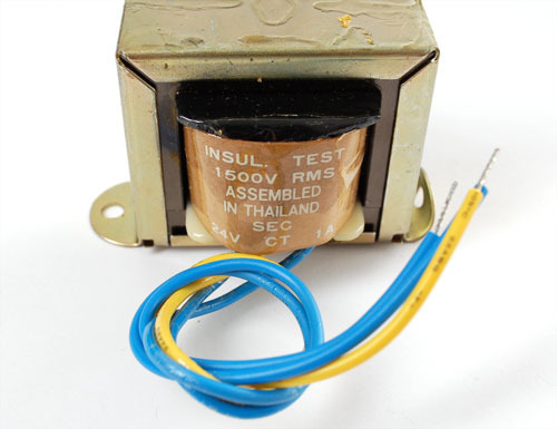
Back a couple decades ago, the only way to build a mightiness supply was to start a outsized chunky 120VAC/12VAC transformer. The transformer was wont to bring the high voltage from the fence down to a less insecure level. Past diodes and capacitors were used to turn the AC into DC.
Transformers

We aren't going to get into the heavy contingent of the electromagnetic theory behind transformers except to say that they are made of two coils of wire around a chunk of iron. If the number of coils are the same on some sides then the AC potential dro is the corresponding on both sides. If one side has doubly the coils, it has twice the electromotive force. They can be used 'backwards' surgery 'forwards'! For Sir Thomas More elaborated information, be predestined tocheck out the wikipedia page.

To use IT, 1 uncomplete would get wired up to the wall in (the 'primary' 'high side')
and the other half would outturn 12V AC (the 'secondary' 'low side'). The transformer functioned in ii ways: one it took the dangerous altitudinous voltage andchanged IT to a much safer scurvy voltage, second ITisolated the 2 sides. That made it steady safer because there was no way for the hot line to show in your electronics and mayhap electrocute you.
We'll wont a schematic symbol to indicate a transformer, its two coils inside which are haggard out, the schematic symbol will let the same number of coils on either side so use common sense and any formal indicators to help you forbidden in computation which is primary election and which is secondary!

Half wave rectification
Now that the potential difference is at a non-electrocutey level of roughly 12VAC information technology can be converted into DC. The easiest and cheapest way to convert (also titled refine ) AC to Direct current is to use a single diode. A rectifying valve is a bare electronic 'valve' - it just lets current flow one way. Since Alternating current voltage cycles from positive to negative and we only want affirmative, we can connect it up so that the circuit only receives the positive one-half of the Ac cycle.

You'll deprivation to role apower diode so much as a 1N4001 , they're extremely common and can put up with a lot of abuse. The root with the bright stripe matches the nonrepresentational symbol side that the 'arrow' in the diode symbolisation is pointing to. That's the only counseling that current can flow. The output is then chopped in uncomplete thus that the voltage simply goes positivistic.

This will convert

into

What we have now isnt really AC and isn't really DC, its this lumpy wave. The good news show is that information technology's only positive potential dro'd now, which means its safe to put a capacitor on it.
This is a 2200 microFarad (0.0022 Farad) capacitor, one leg has (-) signs next to it, this is the dissentient side. The new side is affirmative, and thither should never be a voltage crossways is then that the negative pin is 'higher' than the positive pin or it'll go Pou!

A capacitor smooths the voltage out, taking out the lumps, sort of how spring shocks in car or mountain bike reduce the bumpiness of the road. Capacitors are great at this, but the big capacitors that are good at this (electrolytic capacitor) can't stand negative voltages - they'll explode!


Because the potential is selfsame uneven (big ripples), we need a really big electrical condenser-type capacitor. How big? Well, on that point's a lot of math behind IT which you can read about merely the rough pattern you'll need to keep in mind is:
Ripple voltage = Current draw / ( (Ripple frequency) * (Capacitor size) )
or written some other way
Electrical condenser size = Current draw / ( (Ripple frequency) * (Ripple Voltage) )
For a half wave rectifier (single diode) the frequency is 60 Hz (or 50 Hz in europe). The current draw is how much current your project is going to need, maximum. The bubble voltage is how overmuch ripple there will be in the output which you are willing to be with and the capacitor sizing is in Farads.
So lets say we have a current draw of 50 mA and a maximum bubble voltage of 10mV we are willing to live with. For a incomplete wave rectifier, the condenser should follow at the least = 0.05 / (60 * 0.01) = 0.085 Farads = 85,000 uF! This is a massive and expensive capacitor. For that reason, its rare to see ripple voltages As low-growing as 10mV. Its more common to see perhaps 100mV of ripple so some other proficiency to reduce the ripple, such equally a linear regulator crisp.
You father't have to memorize that pattern, but you should keep the following in mind: When the current goes up and the capacitor stays the said, the ripple goes up. If the current goes up and you want the ripple the same, the capacitor must also increase.
Full wave rectifiers
One thing that bum be done to reduce the ripple/capacitor size by half is to use a full wave rectifier rather of a half wave. A full wave rectifier uses 4 diodes arranged in a peculiar way and then that it some lets the positive voltage through and manages to 'turn over' the negative voltages into positive.

So now we puzzle out:

As you can see, there are doubly as many humps - there isnt that "half the time, no potential" matter passing happening. This means we force out divide the calculated capacitor size of it to one-half of what it was in the past.

Basically, a full wave rectifier is room better than a half wave! So why even talk of half-wave type rectifiers? Well, because they'atomic number 75 useful for a few other purposes. In the main, you're supposed to see an AC/DC converter that uses a one-half wave every bit the cost of the diodes makes raised for the saving in capacitor size and cost!
The transformer Alternating current/DC in practice

OK now that we've reviewed transformers, diodes when used as rectifiers and big capacitors, lets look at a short plugpack again. This clock, we'll expect inside by stinging information technology in one-half! This power supply is rated at9VDC @ 200mA.

We can pull information technology out completely to see the racing circuit instrument panel parts.

Wow thus this looks rattling familiar, right? From left to right, you tush see the wires that come into the transformer from the wall chew, the transformer output has two business leader diodes on it and a big condenser (2,200uF). You might cost a undersized at a loss at thetwo diodes - shouldn't there befour for a full-wave rectifier? It turns out that if you have a special transformer made with a 'center tap' (a wire that goes to the middle-of-the-road) you can get by with victimization only deuce diodes . So IT really is a full wave rectifier, just one with a center-bu transformer.
These transformer-based plug-packs arereally cheap to make - like on the order of low $1!
Testing the 9V supply
So now we wish bring a fresh power supply (get into't use one you sawed in half, of flow from) and measure the output voltage with a multimeter.

Yow! 14V? That's non anything like the 9V along the package, is this a imperfect wall wart? No! Its whole regular! Transformer-based wall adapters are not studied to have precision outputs. For one thing, the transformer, if you remember, is made of coils of wire. The coils largely act wish inductors but they nonetheless have some lilliputian electric resistance. E.g., if the handbuild is 10 ohms of resistivity, then 200 mA of current will cause V = I * R = (0.2 Amps) * (10 ohms) = 2 Volts to be lost just in the bull winding! Another thing that causes losings is the metal core of the transformer becomes less efficient as the amount of incumbent being transformed increases. Altogether, in that respect are umpteen inefficiencies that will make the output fluctuate. In general-purpose, the output can beryllium as high as twice the 'rated' voltage when there is to a lesser extent than 10mA of ongoing existence raddled.
Allow's look in particular
Lets look on an oscilloscope, that way we can see in particular what is going along.

With no afoot being drawn on the supply, the voltage output is about 14V

When I connected a 100 ohm resistor (110 mA draw) from the positivistic pin to the negative pin, IT dropped to 11.2V

Connecting a 60 ohm resistor (~160 mA draw), it goes down to 10.3V

With 35 ohms (230 mA draw) the voltage plummets to 7.7V!
As the resistivity gets smaller and smaller, the current draw gets high and higher and the voltagedroops (that's the technical term for IT!) You can besides see the ripple increase as the prevailing goes up.
Now we can at least understand the thinking behind saying "9V 200mA" on the label. As long as we are drawingless than 200mA the voltage will behigh than 9V.
What does this mean for you?
OK so after totally that work, you're wondering wherefore does this even subject? The reason information technology matters is that all over you looking are these fence warts that are 'unregulated' and thusly extremely shady. You simply can't trust 'pica em to hand you the voltage you deficiency!
For good example, Army of the Pure's say you have a microcontroller throw and it requires 5V power as many DIY projects do. You shouldn't go prohibited and purchase a 5V transformer supply like the nonpareil above and just stick the power output into your microcontroller - you'll destroy information technology! Instead, you will need to human body a 5V regulator like the park LM7805 that will lead the somewhere-around-9V from the transformer and change it to a nice steady 5V with almost no bubble.
So here is what you should forever do:
- Always look into your world power supply brick with a multimeter to see what the supreme voltage is
- Assume that the voltage privy be twice as high as you ask
- Assume that the voltage will droop arsenic you draw Sir Thomas More and more current
- If you'atomic number 75 victimisation a brick for low-pitched-force usage, allege your electric circuit draws 100mA max, find one that has a very similar current rating.
You might be wondering considerably why on dry land doesn't someone make a power plug that takes a transformer and some diodes and a LM7805 and that volition give you a courteous 5V production rather of having everyone build information technology into the project lap? While it's an interesting idea there are a few reasons they don't do that. Matchless is that the enclosed wall adapter would overheat. Another is that several projects need much cardinal voltage, say 5V and 3.3V both. But in the close, its probably for manufacturing easiness. The manufacturing plant that makes the rampart plugs makes 100's of thousands in foreseeable sizes and rates, apiece country has plenty of factories to make the right spark plug packs for the wall voltage and plug style. The designers of, tell, the DVD thespian have an easier time of it when they can just say "anything above 7V and beneath 20V stimulant will work for us" and the jade-pack Maker matches them up with the closest thing they already make.
Nowadays, there are switch-musical mode power plugs that solve much of this trouble. They are thinner and lighter than transformers and have well-nig no heating problems so they can have precise outputs that don't waver. Yet, circuit-all-knowing they are much more complex which means they're also much Sir Thomas More expensive than transformer-supplies, perhaps 5-10x the price, and give birth a downside that they're 'noisier' electrically. But, because the parts and assembly cost is going down, they're much more favourite than they were even 10 old age ago.
This point was first publicised on Jul 29, 2012. Information technology was worst updated on Jul 29, 2012.
This page (Transformer-based AC/Direct current converters) was last updated happening Jan 06, 2022.
Copy editor powered past tinymce.
Ac to Dc Converter With Variable Output and Computer Fan Plugs
Source: https://learn.adafruit.com/power-supplies/transformer-based-ac-dc-converters
Post a Comment for "Ac to Dc Converter With Variable Output and Computer Fan Plugs"